
Point
A single located point, to measure from or to.
Tool reference
Measuret has one rule about naming: no two buttons share a caption. Below is what each one does, grouped exactly as it appears on the ribbon.

Distance
The difference between them is which direction the measurement is allowed to run in. That choice is a metrology decision, not a convenience.
| Tool | What it measures | Use it when |
|---|---|---|
| Point-Point | Straight-line distance between two points you click. | The drawing calls out a distance between two features, in any direction. |
| Horizontal | The horizontal component only. | The dimension is referenced to a horizontal datum and the part may be slightly rotated in the frame. |
| Vertical | The vertical component only. | Heights and depths taken against a vertical datum. |
| Pt-Line | Perpendicular distance from a point to a line. | Standoff, offset and clearance from an edge or datum line. |
| Pt-Arc | Distance from a point to an arc. | Clearance to a curved boundary. |
| Pt-Arc Normal | Distance from a point to an arc, taken along the chord normal. | The direction of the measurement is defined by the arc rather than by whichever way happens to be shortest. |
Shortest distance and fixed-direction distance answer different questions, and picking the wrong one is one of the most common ways an image measurement quietly disagrees with a CMM. Read the guide.
Angle and arc
| Tool | What it does |
|---|---|
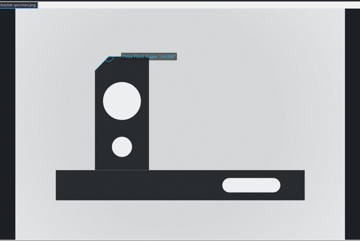
| 3-Pt Angle | An angle from three clicked points: one arm, the vertex, the other arm. |
| 2-Line Angle | The angle between two lines you have drawn. |
| Radius | The radius of the circle through three points on an arc. |
Note the distinction: Radius on this group returns a measured value. Edge Arc in the Draw group creates geometry only — something to measure against later.
Draw
Most real dimensions are taken against a datum that is not itself an edge of the part. These tools let you build it.
A single located point, to measure from or to.
A solid line traced along a real edge of the part.
A dashed datum. It is drawn differently from an edge because it is not an edge — it is a construction you chose.
A guide parallel to an existing line at a distance you type, in the calibrated unit. It keeps a frozen perpendicular witness showing how it was placed.
An arc through three points, as geometry rather than as a reading.
A freehand curve or a connected series of straight segments, for boundaries that are neither line nor arc.
Pick a shape to move, edit or delete it.
Cut a span out of one drawn shape. To remove a whole shape, select it and delete.
Annotation rather than measurement, so they sit on the Main tab with the other image operations.
Analysis
Once two shapes exist, these five tools measure between them as objects — not between two points you happened to click.
| Tool | Returns |
|---|---|
| Closest | The minimum distance between two shapes. |
| Farthest | The maximum distance between two shapes. |
| Perp Closest | The minimum distance measured perpendicular to a reference. |
| Perp Farthest | The maximum distance measured perpendicular to a reference. |
| Intersect | Where two shapes cross. |
Fixed shapes
Fixed shapes work backwards from every other tool, which is why they have their own ribbon tab. You type the size you expect, and Measuret draws exactly that — a circle, a length or an angle — so you can lay it over the feature and see the difference with your own eyes.
It is a fast go/no-go sanity check that needs no checklist and no report.
Display
The overlay is part of the evidence, so its appearance is under your control.
Construction guides — extension and witness lines, angle construction rays, the arc centre cue and intersection witness pairs — are always drawn on the canvas and in a PNG export. An operator needs to see what a reading was taken against, and export is what-you-see-is-what-is-saved.
In the report they are switchable, because a printed sheet is often cleaner without them.
Not sure which tool?
Send us the drawing callout you are trying to satisfy and we will tell you which tool answers it — or tell you honestly if image measurement is the wrong instrument for that dimension.